


Introduction
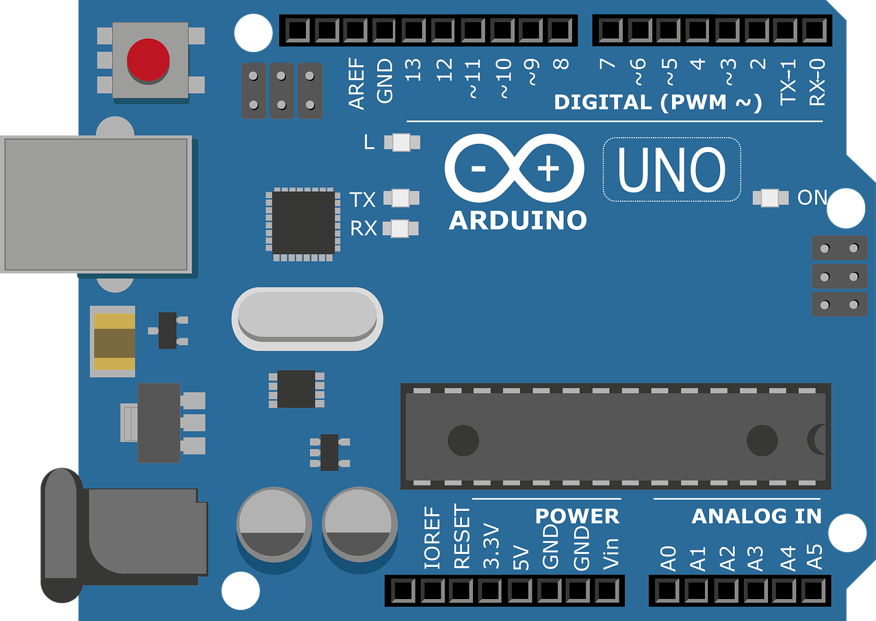
Arduino Uno is a popular development board that has been widely used in communication and digital projects. The latest version of Arduino Uno introduces several new features and improvements that make it an even more versatile and efficient tool for makers and developers.
The SP32: Adding WiFi and Bluetooth
One of the key features of the SP32 is the addition of WiFi and Bluetooth capabilities. This module offers great versatility and functionality, making it a popular choice among developers and engineers. In this article, we will explore some of the main features of the SP32 and how it compares to other microcontrollers in the market.
Powerful 32-bit Microcontroller
The SP32 is equipped with a powerful 32-bit microcontroller, offering more processing power and capacity than its predecessor, the Mega 328p. With a higher clock frequency, the SP32 can handle more complex tasks and perform at a faster speed. Additionally, it boasts an impressive 256 kilobytes of flash memory, which is eight times more than the previous version. This increased memory capacity allows for larger and more sophisticated projects.
An Impressive LED Matrix
One of the standout features of the SP32 is its built-in LED matrix. This module comes with a 12×8 matrix, totaling 96 LEDs. These LEDs can be individually controlled and addressed through the 11 GPIO pins provided. This LED matrix opens up a world of possibilities for visual displays and can be a great addition to various projects.
Versatile Voltage Range
The SP32 stands out with its wide voltage range for power supply. It can be powered by voltages ranging from 5 volts to 24 volts, making it compatible with a variety of power sources and voltage levels. This versatility allows developers to work with different setups and ensures that the SP32 can be easily integrated into existing systems.
Dedicated Connectors for I2C and SPI
To provide even more flexibility, the SP32 features dedicated connectors for I2C and SPI protocols. These connectors, indicated by a white header for I2C and a separate header for SPI, make it easy to interface with other devices and expand the capabilities of the SP32. This means that users can easily connect sensors, displays, and other modules through these standard communication protocols.
The SP32 offers a range of impressive features that set it apart from other microcontrollers. With built-in WiFi and Bluetooth capabilities, a powerful 32-bit microcontroller, an LED matrix, versatile voltage range, and dedicated connectors for I2C and SPI, the SP32 is a versatile and powerful tool for a wide range of projects and applications.
Enhanced Battery Connector
One notable upgrade in the new Arduino Uno is the addition of a battery connector. This connector allows the board to power the internal RTC (Real-Time Clock) and maintain data integrity, making it highly beneficial for projects that require uninterrupted operation. The compatibility with previous versions of Arduino Uno ensures that existing projects can seamlessly transition to the new board.
USB Type-C Connector
The incorporation of a USB Type-C connector in the new Arduino Uno is a practical update. With modern modules predominantly using USB Type-C, the elimination of the mini-B connector is a welcome change. The USB Type-C connector provides faster data transfer rates and better overall performance, enhancing the user experience.
Digital-to-Analog Converter
One standout feature of the new Arduino Uno is the inclusion of a digital-to-analog converter (DAC). This converter is located on pin A4, allowing for precise analog output in projects. The 12-bit resolution of the DAC ensures accurate and detailed analog signals, making it a valuable addition for various applications.
Capacitive Touch Sensors
The new Arduino Uno also features capacitiv
Exploring the Features of the Amplifier Operational Module
Amplifier operational modules are widely used in various fields for amplifying small voltages or working with comparators. In this article, we will take a closer look at the features of one particular module.
The Symbol and Pins
The symbol of an amplifier operational module consists of three pins: a1, a2, and a3. Pins a1 and a2 serve as inputs, while pin a3 functions as the output. This setup makes it highly convenient to work with voltage amplification and comparison.
The Communication Bus
In addition to the amplifier operational module, we can also see the presence of a communication bus. This bus is commonly used in the automotive sector for communication with automobiles. Its inclusion in the module is a notable and fascinating feature.
Price Considerations
Turning our attention to the positive aspects, the price of this module is quite reasonable. When compared to its predecessor, the r3, which was priced at $27.6, the current version is priced at $27.5 during the pre-sale period. Despite being only 10 cents cheaper, this slight reduction portrays a good pricing strategy.
Abundance of Features
Compared to its predecessor, this module boasts an array of features. It includes WiFi connectivity, Bluetooth compatibility, and even a LED matrix. Additionally, it offers eight communication ports, making it highly versatile for different projects.
Opportunities for Improvement
While the module has many positive attributes, there is room for improvement as well. One drawback is the limited number of gpio pins, with only 18 available. Although this may be in line with the Arduino standard, it would have been beneficial to have additional ports for peripherals like GPUs.
Another missed opportunity lies in the utilization of resources. The module features an SP32, which is solely dedicated to WiFi and Bluetooth functions. While this is practical, it restricts the potential use of the SP32 for other purposes.
The amplifier operational module is an excellent tool for various applications. Its reasonable price, extensive features, and ease of use make it a valuable asset. Despite some areas for improvement, it remains a wise investment for those in need of reliable amplification and communication capabilities.
Exploring the Limitations of the SAMP 32 Module
The SAMP 32 module is touted for its impressive 240 MHz speed, but it’s surprising how little of this power is actually utilized. In comparison to the Remesas module, which operates at a mere 48 megahertz but has 384 kilowatts and other features such as a flash SPI memory of up to 8 megabytes, the SAMP 32 falls short in several aspects. Let’s delve deeper into its limitations and potential areas for improvement.
The SPI Port: A Deceptive Dedication
On the surface, the SAMP 32 module appears to have a dedicated SPI port. However, upon closer inspection, it becomes clear that it is not truly dedicated. In reality, the same pins (10, 11, 12, and 13) are utilized for both the SPI port and other purposes. The documentation reveals that only two SPI ports are available, with one already being used to communicate with the CP32. This leaves us with just one SPI port for dedicated use. To enhance the versatility of the module, it would be a worthwhile improvement to include an additional microcontroller with more communication capabilities and allocate a separate dedicated SPI port.
The Misunderstood I2C Port
While the I2C port is indeed dedicated, it is important to note that it has no connection or overlap with the aforementioned SPI port. It is recommended to emphasize this distinction to avoid confusion. The same approach could have been taken with the SPI port, further enhancing the module’s functionality.
Insufficient Memory Capacity
Another area where the SAMP 32 module falls short is its limited memory capacity. Currently, it lacks any external flash memory. In 2023, even the Raspberry Pico boasts up to 16 megabytes of flash memory, while the SP32 module can only offer up to 8 megabytes. Adding a flash memory component to the SAMP 32 module would greatly enhance its storage capabilities.
Differences in Voltage Requirements
A final consideration is the discrepancy in voltage requirements among different microcontrollers. This can pose challenges when integrating various modules into a single system. It is important to account for these differences and ensure compatibility to avoid potential issues.
The Challenges of Power and Compatibility in Arduino and SP32
Power Issues with Arduino and SP32
One of the main challenges when dealing with Arduino and SP32 is the difference in power requirements. While Arduino operates on 5 volts, SP32 operates on 3.3 volts. This poses a problem when trying to connect the two boards directly. If you attempt to connect the SP32 pins to the Arduino pins, there is a high risk of burning or damaging the SP32. Therefore, it is highly recommended to use a voltage translator to establish communication between the two boards.
USB 2.0 Full Speed Limitation
Although the SP32 module claims to have USB 2.0 full speed capability, it is important to note that this feature is currently occupied and not available for use in our programs. This means that we cannot utilize USB communication with other applications or devices. It is essential to be aware of this limitation when programming the SP32 module.
Peripheral Pin Limitations
Another challenge arises when using peripherals that share common pins. This limitation significantly impacts the versatility and flexibility of utilizing different peripherals. For example, the ADC (Analog-to-Digital Converter) pins on Arduino are from A0 to A5, which means that all these pins are occupied when using an ADC. This restricts the ability to use other peripherals that may require these pins. Similarly, the internal LED and I2C (Inter-Integrated Circuit) pins may also have limitations when using certain peripherals.
Why You Should Avoid Using Certain Pins on Your Circuit
When designing a circuit, it is important to carefully choose the pins that will be used for various components and connections. Certain pins may already be connected to other critical components or may have limitations that can affect the functionality of your circuit. In this article, we will discuss the importance of avoiding the use of certain pins and how it can impact your circuit design.
The Issue with Pins A4 and A5
One common mistake that beginners in circuit design make is using pins A4 and A5 without considering their connections. These pins are typically used for I2C communication, which means they are already connected to the I2C bus. If you use these pins for other purposes, you may cause conflicts with the I2C communication and disrupt the functionality of other I2C devices in your circuit.
Touch Sensor Pins A1 and A2
Another consideration when choosing pins is the availability of touch sensors. In many microcontrollers, pins A1 and A2 are dedicated to touch sensors. These sensors rely on the ADC (Analog-to-Digital Converter) to convert the touch input into a digital signal. If you use these pins for other analog connections, you will be unable to utilize the touch sensors effectively.
Blocking Pins with Pan
One phenomenon that often occurs when using certain pins is blocking. This typically happens when the internal thread or interrupt of the microcontroller is occupied by a certain pin or function. For example, if you use the pan function, it may block the corresponding ADC and prevent it from functioning properly. Therefore, it is important to avoid using pins that can potentially block other critical functions in your circuit.
Digital Pin Limitations and the Can Port
When dealing with digital pins, it is important to consider the limitations of the microcontroller. Many microcontrollers have a limited number of digital pins available. If you use unnecessary pins for non-critical functions, you may run out of available digital pins for other important tasks. Additionally, certain pins may be reserved for specific functionalities, such as the Can port for communication. By using these reserved pins for other purposes, you can unintentionally disable important features of your circuit.
The SAMP 32 module, while impressive in terms of speed, falls short in several aspects. By addressing the limitations discussed, such as expanding communication options, clarifying port designations, incorporating additional flash memory, and ensuring voltage compatibility, the module could become a much more versatile and powerful tool for developers and enthusiasts alike.
Power compatibility, USB limitations, and peripheral pin constraints present significant challenges when working with Arduino and SP32. It is crucial to exercise caution and use voltage translators when connecting the two boards to avoid any damage. Additionally, being aware of the limitations in USB functionality and peripheral pin sharing will help optimize the usage of these boards and peripherals. By understanding these challenges and finding appropriate solutions, developers can effectively harness the capabilities of both Arduino and SP32 in their projects.
In summary, careful consideration should be given to the choice of pins when designing a circuit. Certain pins may already be connected to important communication buses or reserved for specific functions. Ignoring these considerations can lead to conflicts, blocking, or the inability to utilize certain features of your circuit. Therefore, it is crucial to study the pinout diagram of your microcontroller and choose the appropriate pins for each component and connection in your circuit.


